For the
composite wing-box (Figure 6-1(b)) with tabulated properties
displayed in Table 6.1 the natural frequencies were determined for a
quadratic tapered wing. Mechanical Properties are also displayed in
the paper published by Eslimy-Isfahany and Banerjee (1997). For a
CAS configuration the fibre orientation on, the top is [+15]2
degrees, bottom [-15]2 degrees and the sides [15/-15]
degrees (CAS is described here)
Using a
pre-processor developed specifically for thin-walled Composite
box-beams based on the formulation presented by Armanios and Badir
(1995) and Berdichevsky et al (1992) the effective rigidities
for graphite/epoxy are obtained to be EI = 4.43 MPa for
bending, GJ= 1.19 MPa for torsion and K=1.75 MPa for
coupled bending-torsion rigidities at the wing root. The effective
rigidities of graphite/epoxy are plotted for multiple ply angles
(Figure 6-3). From this figure the maximum value for the
bending-torsion coupling rigidity is observed to occur at 15
degrees. Along the wing length, the stiffness properties will
vary according to the order of taper.
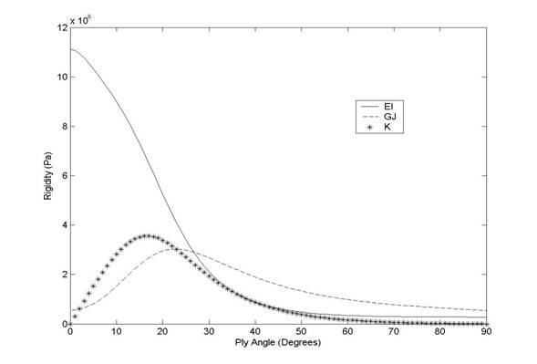
Figure
6‑4: Plot of Rigidities vs Ply
angle for a graphite/epoxy composite.
Table
6‑1: Material Properties of a
graphite/epoxy composite Laminate
|
EL |
206.92 GPa |
Width |
50.8 cm |
|
ET |
5.17 GPa |
Taper Coefficient |
-0.5 |
|
GLT |
3.10 GPa |
Depth |
10.16 cm |
|
nTL |
0.25 |
Taper Coefficient |
-0.5 |
|
Thickness of Layer |
1.016 mm |
Length |
2.03 m |
|
Mass centre offset |
-11.9 cm |
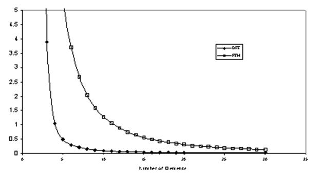
The convergence
test results for the first three natural frequencies of the quadratic
tapered wing are presented in Figures 6-4 to 6-6. The comparison is made
between the numerical results obtained from the DFE with no deviators,
RDFE incorporating the deviator terms and the reference natural
frequencies were obtained from 120 conventional beam Finite Elements.
The FEM model is based on cubic Hermite and linear approximation for
bending and torsion displacements, respectively, and a constant mass
matrix.
Figure
6‑5: Convergence of dually quadratic tapered wing-box
for the first natural frequency.
Figure
6‑6: Convergence of dually quadratic tapered wing-box
for the second natural frequency
Figure
6‑7: Convergence of dually quadratic tapered wing-box
for the third natural frequency.
As it can be seen, in this case, the FEM converges faster than the DFE
when deviators are not used. By including the deviator terms the
convergence rates for all three frequencies increases significantly.
This consistent convergence using the deviators shows that there are no
apparent limitations on these terms. Referring to chapter 5, the
deviators became more effective for higher taper angles. The quadratic
tapered wing is now more complex such that the degrading effects
resulting from numerical error is so small that they do not affect the
positive refining results of the deviators.
A comparison is made between the fundamental natural frequencies of the
graphite/epoxy composite wing obtained from FEM and DFE methods using
different meshes. It is observed that the FEM errors for the first,
second, and third natural frequencies, respectively, are approximately
20, 50 and 50 times higher than the corresponding DFE errors (see Table
6-2).
Table
6‑2: Fundamental frequencies in Hz for a graphite/epoxy
quadratic tapered composite wing
|
Mode number |
120 elements FEM |
10 elements DFE |
ERROR |
10 Elements FEM |
ERROR |
|
1st |
31.74 |
31.73 |
0.025 % |
31.57 |
0.53 % |
|
2nd |
74.36 |
74.40 |
0.050 % |
74.19 |
0.24 % |
|
3rd |
110.44 |
110.50 |
0.056 % |
110.09 |
0.31 % |
6.4.2
Cubic tapered wing.
Let us consider
a dually cubic tapered wing-box with the same mechanical properties as
in the previous example. The FEM and DFE convergence results for the
wings first 5 natural frequencies are presented in Figures 6-7 through
6-11. By implementing a cubic variation the deviators associated with
the DFE method amplify the convergence in contrast to a linearly varying
cross-section of low taper ratio seen previously in Chapter 5.
Figure
6‑8: Convergence of dually
cubic tapered wing-box for the first natural frequency.
Figure
6‑9: Convergence of dually
cubic tapered wing-box for the second natural frequency.

Figure
6‑10: Convergence of
dually cubic tapered wing-box for the third natural frequency.
Figure
6‑11: Convergence of dually
cubic tapered wing-box for the fourth natural frequency.
Only for the
fourth natural frequency (Figure 6‑11)
greater convergence rates are obtained from the FEM, which is irregular
since all other convergence tests favoured the DFE. In order to further
investigate these results, the numerical values for frequencies are
presented in Table 6-3.
Figure
6‑12: Convergence of
dually cubic tapered wing-box for the fifth natural frequency.
Table
6‑3: Natural frequencies for a dually cubic tapered
graphite/epoxy composite wing.
It is observed
from the tabulated results that the DFE is significantly more accurate
than the FEM by a factor of greater than 10. These results are expected
as the DFE formulation is designed to be more accurate for complex
elements such as the present dual cubic tapered model. The natural modes
for the cubic tapered graphite/epoxy wing are displayed in Figure 6‑13
to Figure 6‑17.
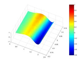
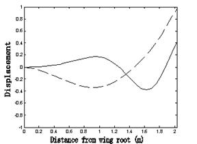
The modes of deformation have been plotted in both 2-D and 3-D spaces
and have been normalized to better distinguish the modes as bending,
torsion or coupled bending-torsion.
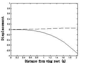
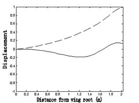
Figure
6‑13: First predominantly
bending mode of vibration for a composite graphite/epoxy cubic tapered
wing in both 2-D and 3-D plots. For the 2-D plot the bending
displacenment is represented by a solid line (-) and torsion is
represented by a dashed line (--).
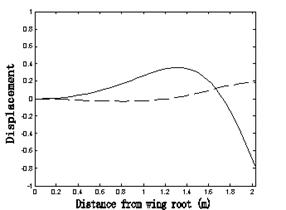
Figure
6‑14: Second predominantly
bending mode of vibration for a composite graphite/epoxy cubic tapered
wing in both 2D and 3-D plots. For the 2-D plot the bending
displacenment is represented by a solid line (-) and torsion is
represented by a dashed line (--).
From the first
two plots in Figure 6‑13
and Figure 6‑14
it can be seen that the modes are predominantly bending with slight
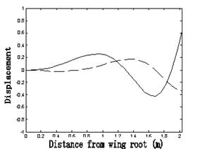
influence of twist. For the higher modes a stronger influence of torsion
is observed particularly for the third mode in Figure 6‑15
where the mode is primarily torsion.
Figure
6‑15: Third predominantly
torsion mode of vibration for a composite graphite/epoxy cubic tapered
wing in both 2D and 3-D plots. For the 2-D plot the bending
displacenment is represented by a solid line (-) and torsion is
represented by a dashed line (--).
Figure
6‑16: Fourth
bending-torsion mode of vibration for a composite graphite/epoxy cubic
tapered wing in both 2D and 3-D plots. For the 2-D plot the bending
displacenment is represented by a solid line (-) and torsion is
represented by a dashed line (--).
The
bending-torsion coupling is apparent in the last two modes extracted, in
Figure 6‑16
and Figure 6‑17
for the fourth and fifth free vibration modes. Although the interpolated
surface plot used in
MATLAB®
is exceptionally useful in visualizing these modes the cubic taper has
been stretched into a rectangular surface such that the 3-D surface
plots are not necessarily to scale, but can still be useful
differentiating the modes as bending or torsion.
Figure
6‑17: Fifth
bending-torsion mode of vibration for a composite graphite/epoxy cubic
tapered wing in both 2D and 3-D plots. For the 2-D plot the bending
displacenment is represented by a solid line (-) and torsion is
represented by a dashed line (--).
The free vibration analysis of thin-walled composite wing-boxes with
quadratic and cubic tapers is presented. By implementing the CAS
configuration and non-coincident mass and shear axes, the wing exhibits
dually coupled vibration. The natural frequencies and modes of
deformation have been extracted using the three methods, conventional
FEM, DFE, and the refined DFE (DFE with deviators). These
deviators take into account the variable geometric and/or material
parameters of the wing model over each DFE. The convergence of the
refined DFE (RDFE) is validated in comparison with the FEM method for
multiple tapered geometries and ply orientations. The RDFE method
provides a much higher convergence rate than classical finite elements.
The corresponding natural modes of vibration were also evaluated and
plotted using the advanced plotting features in MATLAB®. The
programs coded in MATLAB® are discussed in the Appendix.